
Part I · Chapter 04
Placing Components
Parts come from the Catalog tab of the right-hand panel. Drag an item onto the canvas to place it where you drop it, or click it to place it at a default position.
The right-click canvas menu
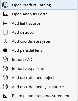
Right-clicking an empty spot on the canvas opens a menu that places the part at that spot:
- Open Product Catalog
- Open Analysis Portal
- Add light source
- Add detector
- Add coordinate system
- Add paraxial lens
- Import CAD
- Import .seq / .zmx
- Add user-defined object, for a custom or uploaded optic
- Add user-defined light source, for a custom source
- Beam parameters measurement, the Gaussian Beam tool
Quick Add
The Quick Add row at the top of the Catalog tab holds the most common parts: Detector, Light Source, Paraxial Lens, Custom Lens, Point Source and Screen Source.
The Optics catalog
Below Quick Add, the Optics category lists the part types: Mirror, Prism, Aperture, Mask, Lens, Filter, Beam Splitter, Grating and Window. Placing one opens a dialog with default parameters that you can change before or after placing. Searching and filtering the catalog is covered in The Optics Catalog In Depth.
The Parts tree
The PARTS tree on the left lists everything in the setup. Each part shows its coordinate systems as child nodes; the setup's global coordinate system (GCS) is the root.
Every part gets a short label: LS for light sources, D for detectors and OP for optical parts, followed by a number, for example LS1, D1, OP5. A group appears as one node with its members underneath.
Grouping parts
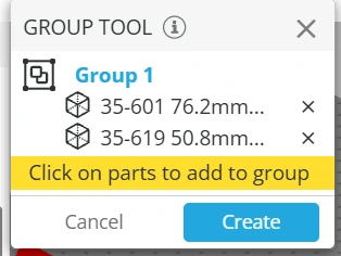
Click Group in the toolbar, then click the parts to include. The panel lists them under a group name; click Create to make the group. Right-click a group to ungroup it.
After placing a part
Select a part in the viewport or in the tree to see its settings in the Inspector: Move & Rotate first, then the sections for that part type.
The Inspector header has Duplicate and Delete (not available for groups). A light source also has a lightbulb toggle that switches that one source on or off; it works once lights are switched on globally with the Light button in the toolbar.
Any surface can become a detector
Right-click an optical surface in the Parts tree and choose Add surface as a detecting surface. The surface then appears in the Analysis Portal like a detector, so you can check the irradiance on a lens or mirror face without placing a detector. Remove surface from detecting surfaces undoes it.
Detector size
A new detector is 50.8 mm × 50.8 mm. Change its size in the Inspector with X Half Width and Y Half Width (25.4 mm each by default). The pixel resolution is not a property of the detector; you set it per analysis in the Analysis Portal.
Arrays of elements
Select an optic, a CAD part, a laser source or a group and open the Array of Elements section in the Inspector to repeat it on a grid, for lenslet arrays, detector arrays and similar structures.
Availability: Array of Elements is a Professional-tier feature and is not enabled on every account. If the section is missing from the Inspector, contact support.
Enabling an array
Switch Is array of elements on. An optic or CAD part starts as a 2×2 grid sized to the part; a laser source starts as a 5×5 grid.
Area shape
- Rectangular: set Half size W/H, the footprint of the array.
- Elliptical: set Radius X/Y. Available for laser sources only.
Sampling and count
- Sampling: set the Period X/Y, the spacing between neighbors.
- # of elements: set the Count X/Y.
The two stay in sync: changing the period updates the count, and changing the count updates the period. Shrinking the footprint tightens the period so that elements stay inside it.
Element limits
An array holds at most 100 elements on a catalog optic and 26 on a CAD part. If your settings would exceed that, the count is reduced and a notification tells you. Laser arrays have no such cap.
Edit shape (laser arrays only)
Edit shape opens a form for a custom surface shape applied to every element. The shape is used during simulation and is not shown in the 3D view.


