
Part II · Chapter 12
Coordinate Systems (CS)
Every part has a position and an orientation, and both are measured against a coordinate system. Once a layout is folded, off-axis or built from sub-assemblies, choosing the right coordinate systems is what keeps it manageable.
GCS and LCS
- GCS, the global coordinate system. There is one per setup, at (0, 0, 0). It cannot be moved, rotated, renamed or deleted. The breadboard lies at y = 0, and a new part is placed 10 mm above it at the point you clicked.
- LCS, the local coordinate system of a part. It defines the part's position and orientation, measured against the GCS by default or against another part's coordinate system if you link one.
A part can carry extra named coordinate systems, for example one aligned to a surface or an edge. One of them is the working LCS at any time; the others can be promoted later.
Coordinate systems in the tree
The GCS, every LCS and every extra coordinate system appears as a node in the PARTS tree. You can show, hide, rename and zoom to each one. When a part's Move & Rotate panel is open, the viewport draws a dashed line from the part to its reference coordinate system.
Move & Rotate
Select a part to see its Move & Rotate panel:
- Lock move & rotate: when checked, the fields are disabled and edits show a warning.
- Position X, Y, Z, in mm or inches.
- Rotation X, Y, Z, in degrees or mrad.
- Reset, which returns the part to its original transform.
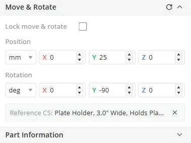
Position and rotation are always relative to the part's reference coordinate system: the GCS, or the coordinate system you linked. Values update as you drag the part in the viewport.
Linking a part to another part
To make one part's position follow another's, for example a detector that should stay behind a lens:
- Select the part.
- In Move & Rotate, click Press to pick reference CS.
- Click the part or coordinate system to reference in the viewport. Click the button again to cancel.
A reference card then names the reference coordinate system, and the position and rotation fields read relative to it. Click the X on the card to remove the link.
Some parts cannot take a reference: members of a group, locked parts, and coordinate systems anchored to a chief ray.
Adding a coordinate system marker
Add → Coordinate System in the right-click canvas menu places a standalone coordinate system where you clicked. Move, rotate, rename or link it like any other part.
The Add CS tool
To align a coordinate system with a feature of an existing part, select the part and use the Add CS tool. It has two steps:
- Select Point, the origin. Pick an Edge/Axis or a Surface in the viewport, or type the coordinates. Optomechanics and CAD parts default to edge picking, optics to surface picking.
- Select Axes, the orientation, by one of: Direction by face, Direction by edge, Direction by points (two picked points), Direction by reference CS (copy another coordinate system) or Direction by values (type two axis vectors; the tool makes them orthogonal and derives the third).
Each axis can be flipped. Give the coordinate system a name and click OK.
The coordinate system menu
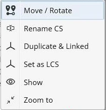
Right-click a coordinate system in the tree:
| Item | What it does |
|---|---|
| Move / Rotate | Opens the part's Move & Rotate panel with this coordinate system selected. |
| Rename CS | Renames the coordinate system. |
| Duplicate & Linked | Creates a copy at the same position, makes it the part's reference and links the part to it. |
| Set as LCS | Makes this coordinate system the part's working LCS. |
| Show / Hide | Shows or hides it in the viewport. |
| Remove | Deletes an extra coordinate system or a standalone marker. The working LCS cannot be removed. |
| Zoom to | Centers the camera on it. |
| Re-anchor on chief ray / Detach from chief ray | For chief-ray coordinate systems only, see below. |
The GCS cannot be moved, referenced, duplicated or replaced.
Chief ray coordinate systems
A chief ray coordinate system follows the chief ray of a light source and moves itself after every run. Use it for a detector or a fold mirror that should stay on the beam wherever upstream parts send it.
- Re-anchor on chief ray attaches it to the ray again after a change; a warning appears if the source no longer exists.
- Detach from chief ray turns it into an ordinary fixed coordinate system.
A chief ray coordinate system cannot be linked to a reference.
Availability: chief ray coordinate systems are not enabled on every account. If the options are missing, contact support.
Quick reference
| To… | Do this |
|---|---|
| See a part's position relative to the world origin | Open Move & Rotate with no reference set. |
| Make one part follow another | Move & Rotate → Press to pick reference CS, then click the other part. |
| Remove that link | Click the X on the reference card. |
| Drop a marker | Add → Coordinate System. |
| Align a coordinate system to a surface, edge or direction | Use Add CS. |
| Make an extra coordinate system the working one | Right-click it → Set as LCS. |
| Insert a reference between a part and its current reference | Right-click its coordinate system → Duplicate & Linked. |


