
Part II · Section 13A
Imaging System (Field and Stop)
The Imaging System tool treats a group of parts as one imaging system and computes its first-order properties: entrance and exit pupils, focal length, magnification and more.
Two terms it uses:
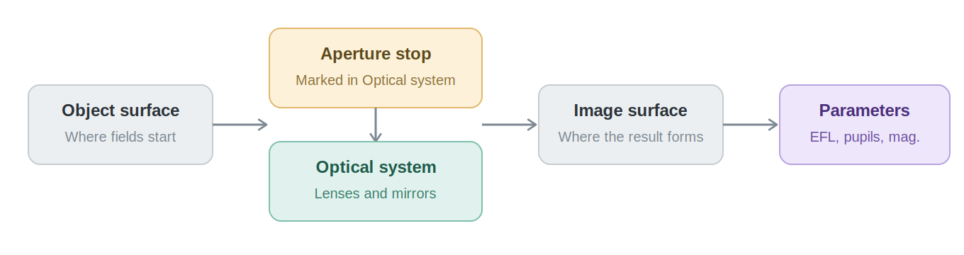
- Aperture stop: the opening or element edge that limits the cone of light reaching the image. You mark it yourself in the tool.
- Field: a point on the object at which the system is evaluated. Checking several fields, not only the one on the axis, reveals vignetting and off-axis aberrations.
Creating an imaging system
- Select the parts of the system in the viewport.
- Group them.
- Right-click the group and choose Create Imaging System, or click the button of that name in the Inspector.
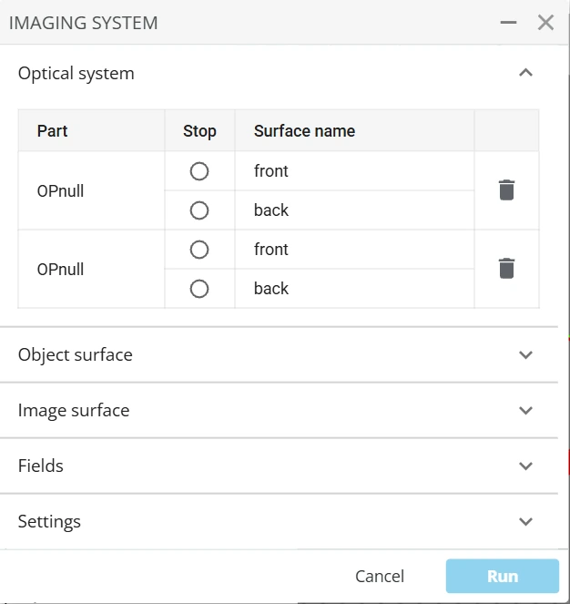
The Imaging system panel opens with five sections: Optical system, Object surface, Image surface, Fields and Settings.
Availability: the Imaging System tool is not enabled on every account. If Create Imaging System is missing, contact support.
Optical system and the Stop
Click parts in the viewport to add them to the Optical system table. Each row lists the part, its surface and a Stop radio button. Mark exactly one surface as the Stop.
- The Stop cannot be on a paraxial lens, on a polygon-shaped surface or on a mask.
- If the Stop is on an Aperture part, the Stop radius in Settings is taken from that aperture. On any other surface, you enter the radius in Settings.
- While the tool is open, a temporary IS STOP Aperture appears in the Parts tree at the Stop. It is removed automatically.
Object surface and image surface
Each has a position and a shape, Plane or Conic; Conic adds a deformation profile. The From infinity switch is present but locked: the object is always at a finite distance.
Fields
Each field has a name and a Position, an X/Y point on the object surface in mm. Angles is shown but not yet supported. + Add field adds one; the trash icon removes one.
Settings
- Stop radius, as described above.
- A wavelengths table for the run.
- Optional analyses: Vignetting (needs a field off the axis), Chromatic focal shift (needs two wavelengths), Distortion, Lateral color (needs two wavelengths and a field off the axis) and Ray aberration (with a sample count). An analysis whose requirement is not met is disabled, and its tooltip says why.
Results
Click Run. The Imaging system parameters panel opens, and you can reopen it later from the group's right-click menu under Parameters/Characteristics. It shows:
- Entrance and exit pupil position and radius.
- Focus and principal planes, relative to the system and in world coordinates.
- Focal length (EFL) and magnification.
- Nodal points, when available.
- Cone half angle and position per field.
- Charts and tables for the optional analyses you enabled, with any warnings.
The results are not recomputed when you change the setup. Run again after a change.
Acronyms
| Term | Meaning |
|---|---|
| EFL, BFL, FFL | Effective, back and front focal length |
| NA | Numerical aperture |
| MTF | Modulation transfer function |
| PSF | Point spread function |
| RMS | Root mean square |
| BOM | Bill of materials |
| GCS, LCS | Global and local coordinate system |
| CAD | Computer-aided design |
| IES | A file format for measured light sources (Illuminating Engineering Society) |
| BSDF | Bidirectional scattering distribution function, the scattering models |


