Surface scattering refers to the phenomenon where light interacts with irregularities or structures on the surface of a material, causing the light to deviate from its original path. When light encounters a rough or textured surface, it gets scattered in different directions due to the interaction with surface features. In the real world, surface scattering is observed in various situations: rough surfaces, optical diffusers, anti-glare coatings, and residue scattering on optical surfaces.
In the field of optical design, surface scattering is an important consideration in various areas:
Display Technology: Surface scattering can significantly affect the readability and visual quality of displays. Designers of devices like LCDs, OLEDs, and touchscreens carefully select materials and coatings to minimize surface scattering and enhance image clarity.
Projection Systems: When projecting images or videos onto screens or surfaces, surface scattering can cause undesirable effects, such as the loss of image sharpness and reduced contrast. Optical designers utilize specialized coatings and materials that minimize scattering and optimize image projection.
Solar Energy: In solar panel design, reducing surface scattering is crucial to maximize light absorption. By minimizing surface roughness and applying anti-reflective coatings, designers aim to reduce light scattering, increase light transmission, and enhance the efficiency of solar cells.
Optical Coatings: Optical coatings control the reflectance and transmittance of light. By carefully engineering the surface structures and properties of coatings, designers can minimize scattering and enhance the overall performance of lenses, mirrors, and other optical components.
In 3DOptix software, scattering properties can be defined for each optical and mechanical surface. This covers all possible scattering scenes for all areas of optical design.
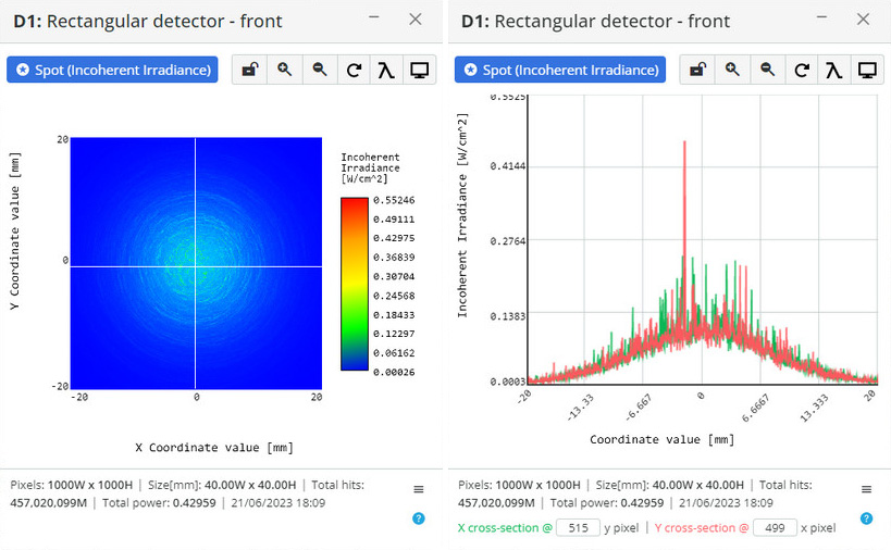
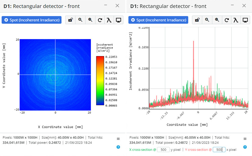
- Gaussian scattering:
Where
\Iota(\theta) – Intensity in the \theta direction.
\Iota_0 – Intensity in the specular direction.
\phi – azimuthal scatter angle measured from the local x-axis.
\sigma_x – standard deviation of the Gaussian distribution parallel to the local x-axis.
\sigma_y – standard deviation of the Gaussian distribution parallel to the local y-axis.
\theta – polar angle.
Note: Gaussian scattering is modeled around the specular reflection or refraction direction.
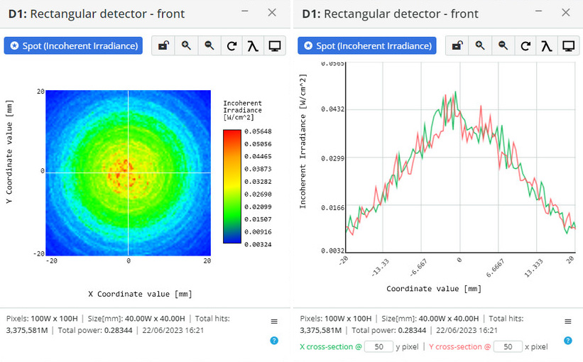
- Lambertian:
Where
\Iota(\theta) – Intensity in the \theta direction.
\Iota_0 – Intensity in the specular direction.
\theta – polar angle.
Note: Lambertian scattering is modeled around a normal to scattering surface.
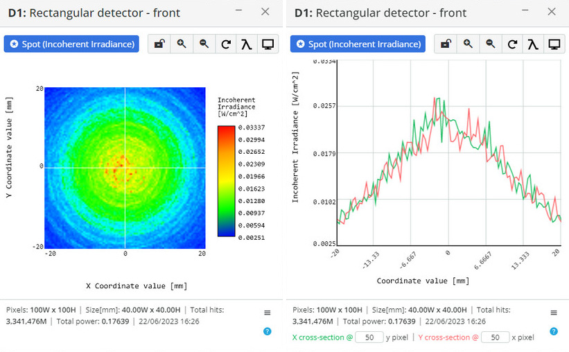
- Cos Nth:
Where
\Iota(\theta) – Intensity in the \theta direction.
\Iota_0 – Intensity in the specular direction.
\theta – polar angle.
\Nu – distribution parameter.
- ABg:
Note: ABg scattering is modeled around the specular reflection or refraction direction.