Home

Laser Beam Steering

Laser Beam Steering

Laser beam steering has applications in materials processing, optical tweezers, and other precision scientific measurements. Steering can be achieved using static systems for simple repeatable measurements and dynamic systems employing electronically controlled components. The precise positioning of the laser spot on its intended target can be a difficult task for dynamic systems as jitter in the laser itself along with the motion system can impact performance.  Observing and analyzing the spatial profile of the laser spot can help realize high-performance systems.
In the3DOptix cloud-based simulation tool steering systems can be constructed and spot profiles analyzed using the analysis features. We will look at a few cases for beam steering to determine the tradeoffs in each.
The first optical system consists of a static steering system with the following components:
  1. Thorlabs PF20-03-P01 Protected Silver Mirror
  2. Thorlabs PF20-03-P01 Protected Silver Mirror
  3. Light Source
    • Plane Wave
    • Circular, 5 mm radius
    • 633 nm wavelength
    • Power, 1 W
  4. Detector: Spot Analysis
    • Spot: Coherent Irradiance
    • Analysis Rays: 1 million
    • 200×200 pixels
You can see the image of our optical system below. The 3DOptix simulation file can be downloaded to see additional information about the optical system such as component spacing and analysis detectors.
Due to the shape of the design, this is known as the figure 4 configuration. This design is more compact due to the geometry and the two mirrors give dual X/Y control of the laser beam. The spatial extent to which the laser beam can be steered will be limited by the size of the second mirror. In angle space, a shift in either the X or Y direction by the first mirror and the same shift in the second mirror will steer the beam while keeping it straight (In the 3DOptix coordinate system).
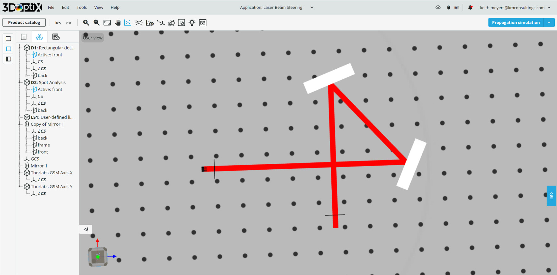
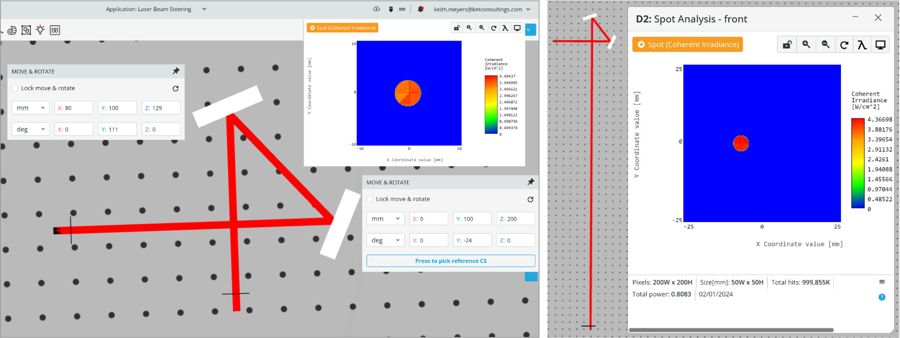
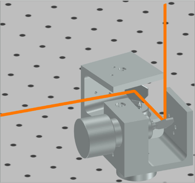
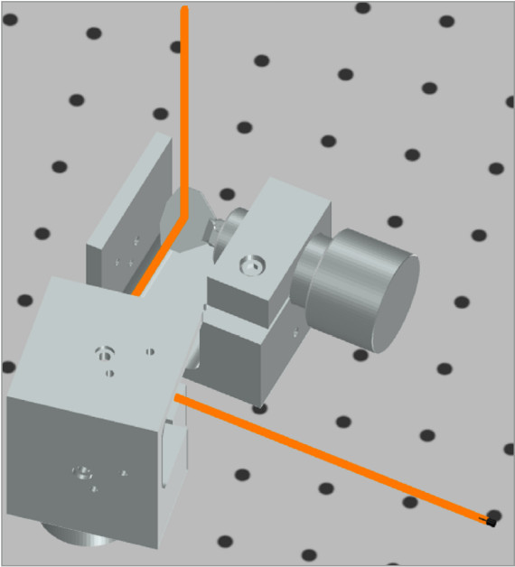
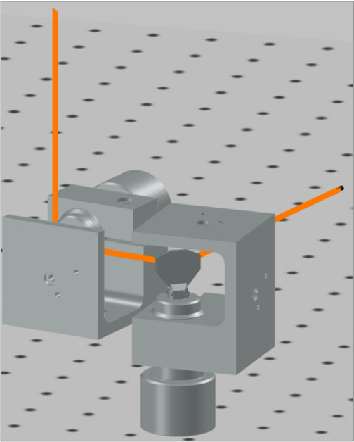
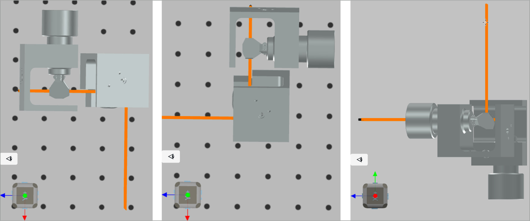
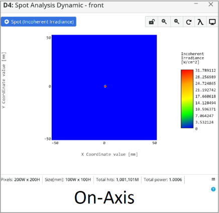
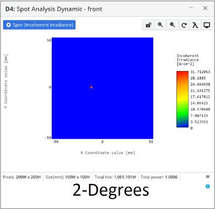
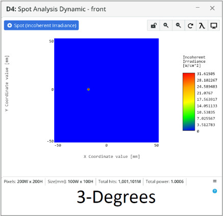
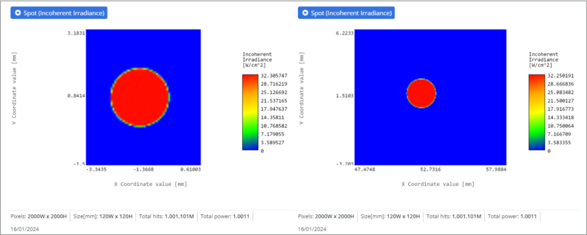
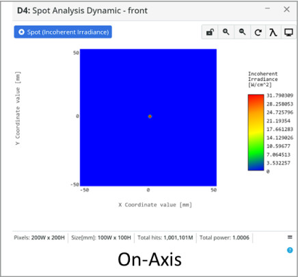
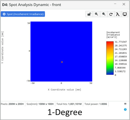
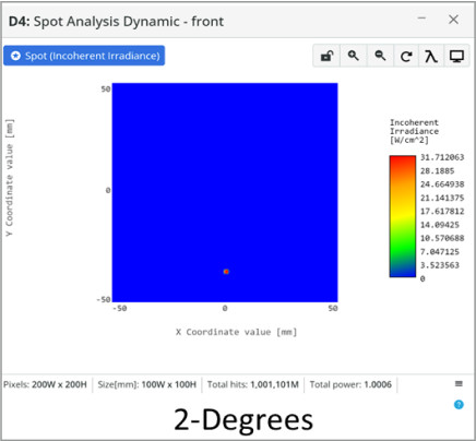
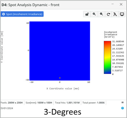
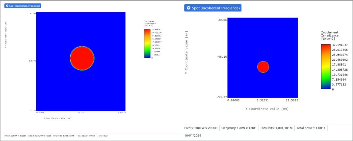
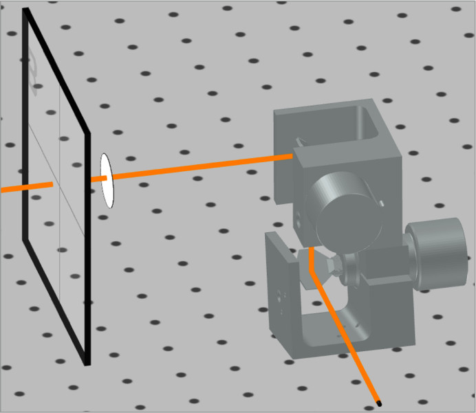
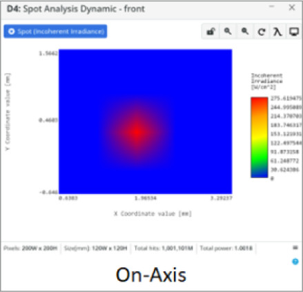
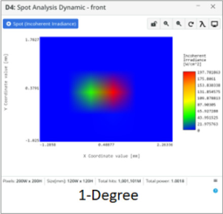
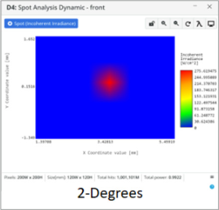
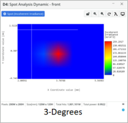
Images of the nominal configuration, and shifted configuration (2-degree shift in mirrors 1 and 2) are shown below. The spot detector has been moved 1080 mm from mirror 2 to show the straightness of the beam and the accurate horizontal shift.
This setup is useful for alignment applications steering the beam onto the target and keeping the incident angle zero with respect to the target surface.  This can be important if Fresnel reflections at steep angles are undesirable, such as testing the spectral sensitivity of photo-detectors. The spatial profile of the laser beam is unchanged at the target plane maintaining high spatial quality. Additional adjustments can be made, but the repeatability of this steering system is low.
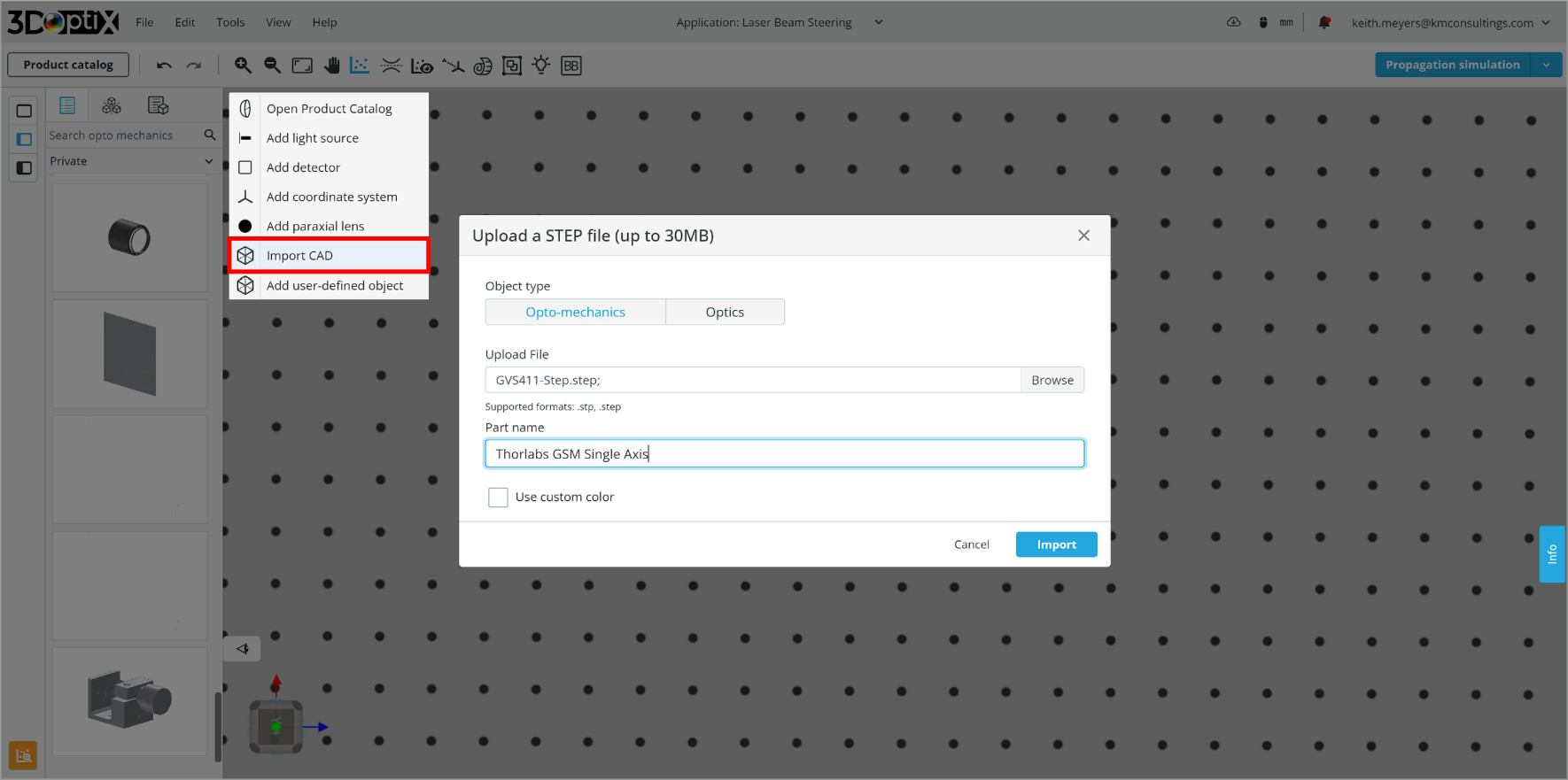
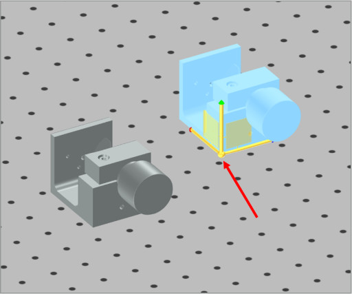
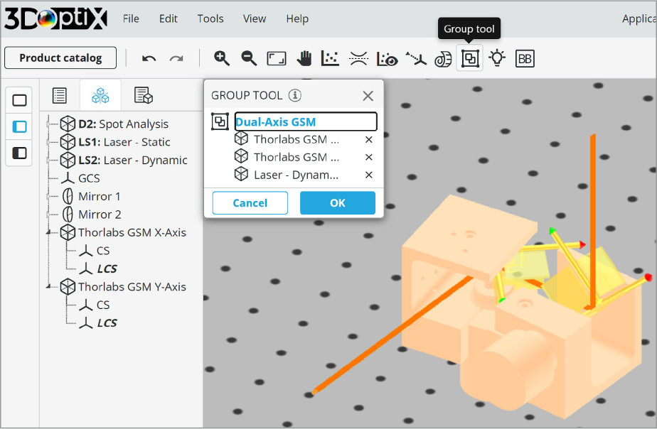
The next optical system consists of a dynamic steering system with the following components:
  1. Thorlabs GVS41, 1D Large Beam (10 mm) Diameter Galvo System
  2. Thorlabs GVS41, 1D Large Beam (10 mm) Diameter Galvo System
  3. Light Source
    • Plane Wave
    • Circular, 2 mm radius
    • 633 nm wavelength
    • Power, 1 W
  4. Detector: Spot Analysis
    • Spot: Incoherent Irradiance
    • Analysis Rays: 1 million
    • 200×200 pixels
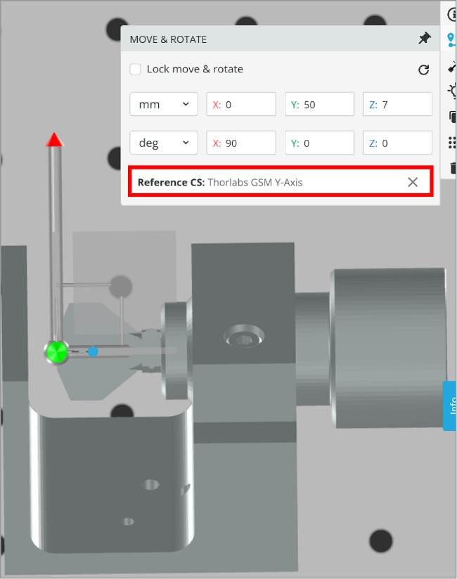
We want to simulate a dual axis galvo-scanning mirror (GSM) and to do this we will upload two individual single axis GSM CAD files. The reason for this is CAD files are not able to separately move individual parts, so the entire object must be moved. With this method, we can use the two CAD files to simulate individual mirror motion.
Now that the CAD models are uploaded, we must make a change to their LOCAL COORDINATE SYSTEM. As shown in the image the LCS is attached to the bottom corner of the GSM, but that will make it difficult to rotate the mirrors for laser steering. What we want is for the LCS to be at the mirror plane, so an angular shift is correct.
A surface needs to be chosen for a new LCS that when rotated it correctly rotates the mirror without any angular errors.  We can select the outer edge of the mirror to create the coordinate system.  This way the mirror rotates perfectly with respect to its front face.  The same process will be done to the second GSM. 
Now there are two GSM’s that are able to be rotated with respect to the correct optical surface; the mirror. 
We must find a position that centers the light source at the center of the first GSM.  Once properly aligned the light source reference CS is removed in order to rotate the mirror freely without moving the light source.
After aligning the light source and two GSM CAD objects the simulated dual axis GSM is now complete.

With the three objects aligned, we need to group them together using the GROUPING TOOL. This will prevent any unintentional misaligning and make it easier to reposition the system.

After grouping, the group can be moved in the 3D layout or using the MOVE/ROTATE ribbon button. This will make it simpler to rotate the system and direct the light output along another axis.

The images below show the dual-axis GSM easily rotated to output the light along any axis or arbitrary direction. Once we reach the desired position, we can then move each GSM individually by clicking on them in the outliner bar on the right of the 3D layout.
Now analysis of this steering system can be conducted.
The x-axis mirror will be moved through 3 degrees and the detector will be placed at 100 mm from the dual-axis GSM to show the change in steering extent. The limited angles are due to the small form factor of the mirror.
The laser spot only shifts 17 mm total with the short distance from the GSM to the target plane. The position the spot lands on the detector is non-linear with respect to the input angle, so the shift gets larger with greater angles. The laser spot spatial profile does not change significantly.
The detector will be moved farther away to show how the steering extent increases. The new position is 500 mm from the dual-axis GSM. This time the y-axis mirror will be moved through 3 degrees.
The detector in the y-axis mirror tilted 3-degree configuration is increased to 120 mm from 100 mm to capture the laser spot.  The laser spot now moves greater than the 100 mm of the detector as we have increased the optical path length and the laser spot spatial profile does not change significantly.
This beam steering system has different limits than the static steering system previously covered.  The GSM will not create a direct incidence beam at the target plane so there will exist some incident angle, and the spatial extent that the beam can cover will be limited by the optical path length from the GSM to the target plane as has been shown.

The last optical system will be a simple example of a more complex system. The F-Theta lens is a lens system that creates a flat focal plane tangent to the optical axis and creates a linear relationship between the angle out and the target plane position. This removes off-axis spot size variations over a certain input angle range and the need for algorithms to calculate the non-linear position on the target plane.

For a normal spherical lens, the focal plane is curved and the best spot size performance occurs on-axis when scanning a collimated beam. An F-Theta lens system creates a flat focal plane that generates the same spot-size performance over a range of input angles for the same collimated beam.

The last optical system consists of a paraxial lens with the following components:
  1. Paraxial Lens, 25 mm FL
  2. Light Source
    • Plane Wave
    • Circular, 5 mm radius
    • 633 nm wavelength
    • Power, 1 W
  3. Detector: Spot Analysis
    • Spot: Incoherent Irradiance
    • Analysis Rays: 1 million
    • 200×200 pixels
The dual-axis GSM used in the dynamic laser beam steering system is a great way to demonstrate scanning a collimated beam through an F-Theta lens system.  The paraxial lens will simulate the performance that would be realized over the scan range of the collimated input beam.

The paraxial lens scanned with the collimated laser beam using the dual-axis GSM provides a good example of this system but is not exact. The steering ability matched with spot size performance and positional linearity makes these very useful in applications where minimum spot size must be maintained over the scan angle, such as laser engraving. Similar to the dual-axis GSM the F-Theta input aperture diameter and focal length will be the limiting component for the steering extent.

The three laser beam steering systems overviewed have a variety of benefits, limitations, and design types.  The specific system chosen will be a function of needed performance and laser output requirements for the application.  Simulating laser beam steering systems to confirm or improve performance is a great method to create high-quality optical systems.

mascot-1-1

3DOptix works
only on desktop!

Please go to 3doptix.com on a
desktop device, using the
Chrome or Edge browser

Available on January 30th, 2023