Fourier optics is a branch of optics that utilizes the principles of Fourier analysis to understand and manipulate the behavior of light. It is a powerful mathematical framework that provides a convenient way to describe the propagation and diffraction of light, as well as various optical systems.
At its core, Fourier optics is based on the concept of the Fourier transform, which is a mathematical operation that decomposes a complex function (in this case, an optical field) into its constituent frequency components. This decomposition allows us to analyze and understand how light interacts with various optical elements, such as lenses, apertures, and diffraction gratings.
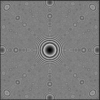
One of the fundamental concepts in Fourier optics is the Fourier transform itself. By applying the Fourier transform to an optical field, we can determine its spatial frequency content, which provides information about light distribution across different spatial frequencies. This information is particularly useful for characterizing diffraction patterns and understanding the effects of optical aberrations.
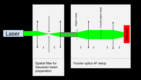
Fourier optics also enables us to manipulate optical fields through various operations. For example, by applying a Fourier transform to an input field and then applying a phase modulation in the Fourier domain, we can achieve various desired effects, such as spatial filtering, beam shaping, and holography. These operations are crucial in imaging, signal processing, and optical information processing.
Furthermore, Fourier optics plays a significant role in understanding and designing imaging systems. The concept of the optical transfer function (OTF) is central to this field. The OTF describes the imaging performance of an optical system and provides insights into parameters like resolution, contrast, and depth of field. By analyzing the OTF of an imaging system, we can optimize its design and improve its performance.
In recent years, Fourier optics has seen significant advancements due to the rapid progress in computational power and digital imaging technologies. The ability to perform fast Fourier transforms (FFT) and utilize numerical methods has revolutionized the field, allowing for complex simulations, wavefront analysis, and the development of advanced optical systems.
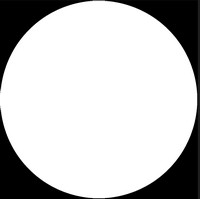
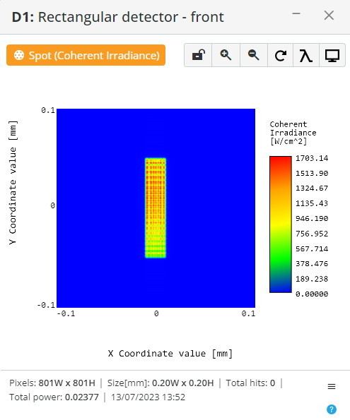
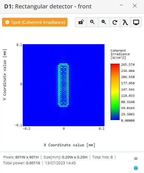
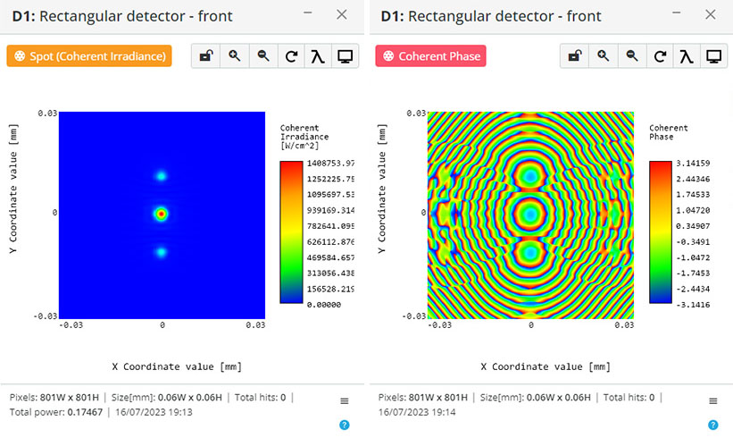
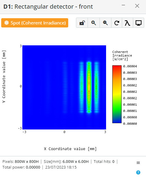
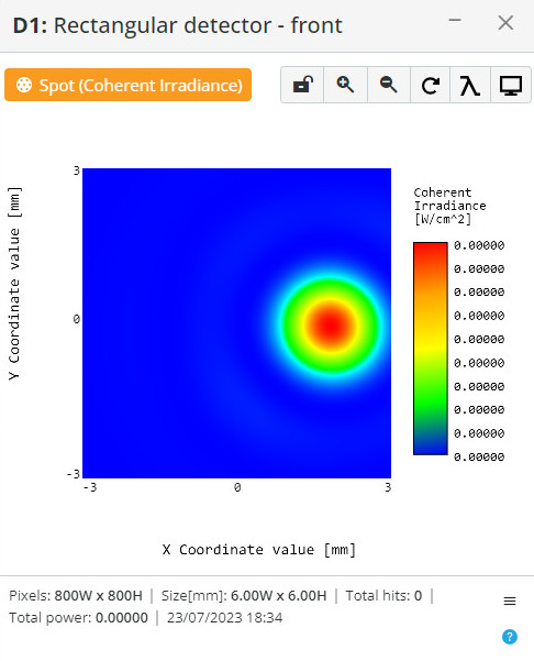
In 3DOptics software, simulation of the Fourier optics models is possible due to the scalar Huygens propagation algorithm and amplitude and phase masks. An optical scheme can be created by loading files pre-designed in the Matlab of amplitude or phase masks or both.
The 3DOptics software allows the simulation of Fourier optics models using the scalar Huygens propagation algorithm and amplitude and phase masks. With this software, users can create optical schemes by loading pre-designed files containing amplitude masks, phase masks, or both, which are implemented within the Matlab environment. This enables accurate modeling and analysis of various optical phenomena and systems based on Fourier optics principles. Mask files are transferred from Matlab to 3DOptix using the “png8” or “png16” raster graphic formats. These formats ensure efficient and accurate transmission of the mask data, allowing seamless integration of the mask files into the 3DOptix software for further analysis and simulation.