Home

Astronomical Telescope Design I

Astronomical Telescope Design I

Astronomical telescopes come in various designs, each tailored to specific observational needs. Refracting telescopes, also known as refractors, utilize lenses to gather and focus light for astronomical observation. The primary optical components include an objective lens, which collects and converges incoming light, and an eyepiece that magnifies the focused image for observation. Refractors offer advantages such as crisp image quality and low maintenance, but they may suffer from chromatic aberration, where different colors of light are not focused uniformly, resulting in color fringing. These are the types normally found in stores and online for amateur astronomers.
In the 3DOptix cloud-based simulation software refractive, reflective, and catadioptric telescope designs are able to be built and analyzed using the convenient 3DOptix tools. We will design and overview the simple Kepler telescope to see how this can be achieved in a comprehensive manner.
Our optical system will demonstrate the Kepler telescope design consisting of the following components:
  1. Light Source
    • Plane Wave
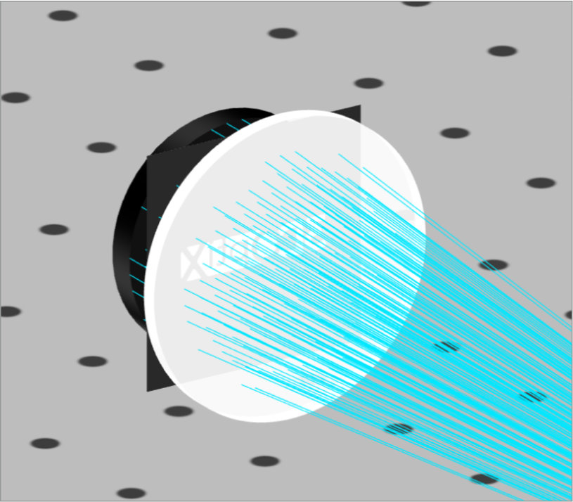
    • Circular, 5 mm radius
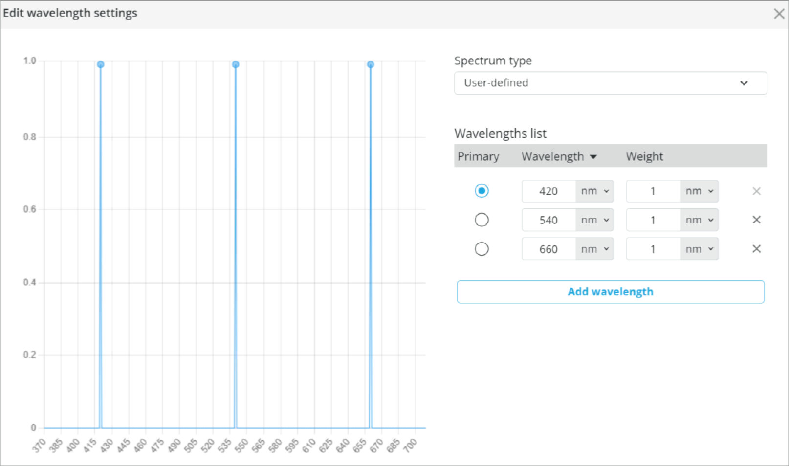
    • Wavelength: 633 nm
    • Power 1 W
    • Unpolarized
  2. Thorlabs LA1301, 250 mm FL Plano-Convex
  3. Thorlabs LA1131, 50 mm FL Plano-Convex
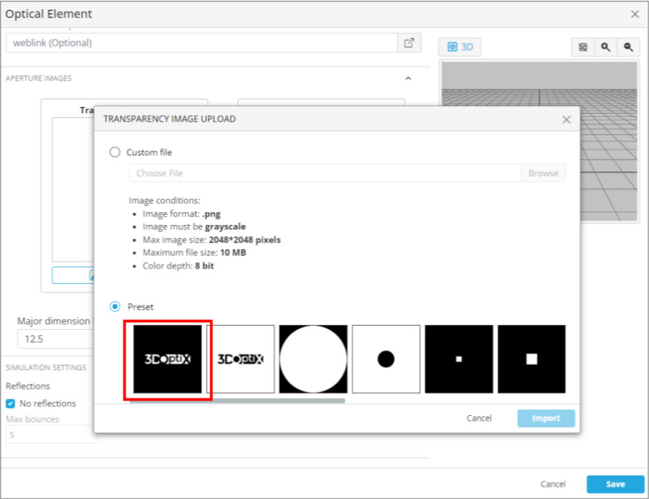
  4. Field Stop, 12.7 mm
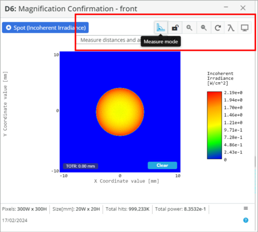
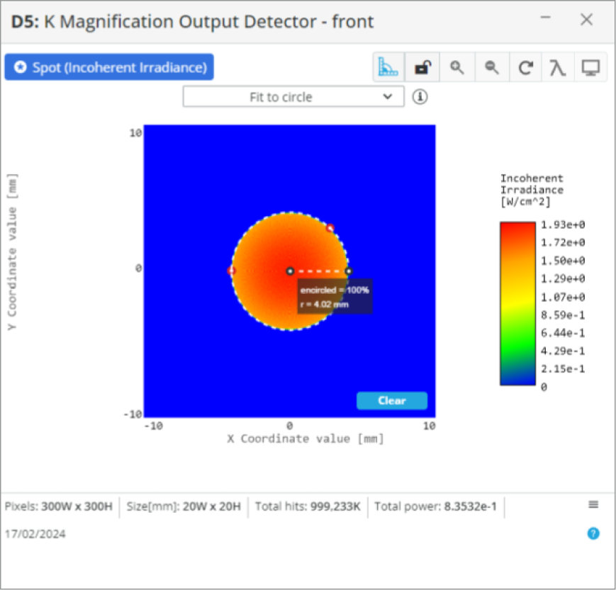
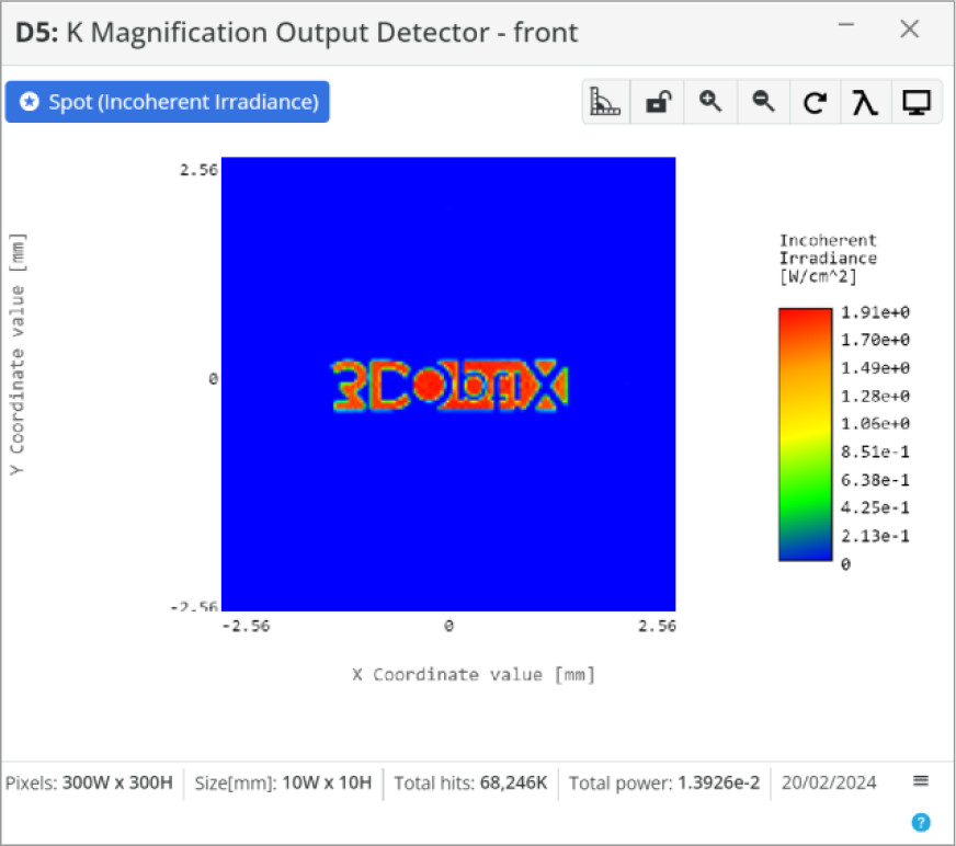
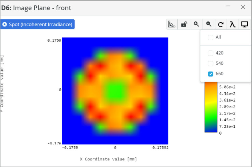
  5. Detector: Spot Analysis
    • Spot: Incoherent Irradiance
    • Analysis Rays: 1 million
    • 300×300 pixels
You can see the image of our optical system below. The 3DOptix simulation file can be downloaded to see additional information about the optical system such as component spacing and analysis detectors. The objective is the large front lens and the eyepiece is the smaller rear lens.

This telescope design can also be used as a beam expander/reducer for laser applications. 

Some characteristics of the Kepler telescope:

  • Longer system due to the two positive lenses
  • Heavier due to the need to flip the image using prisms or mirrors
  • Good magnification for astronomical viewing

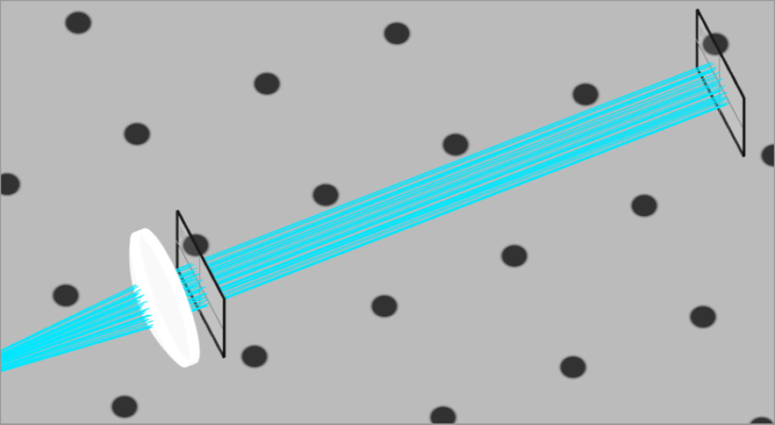
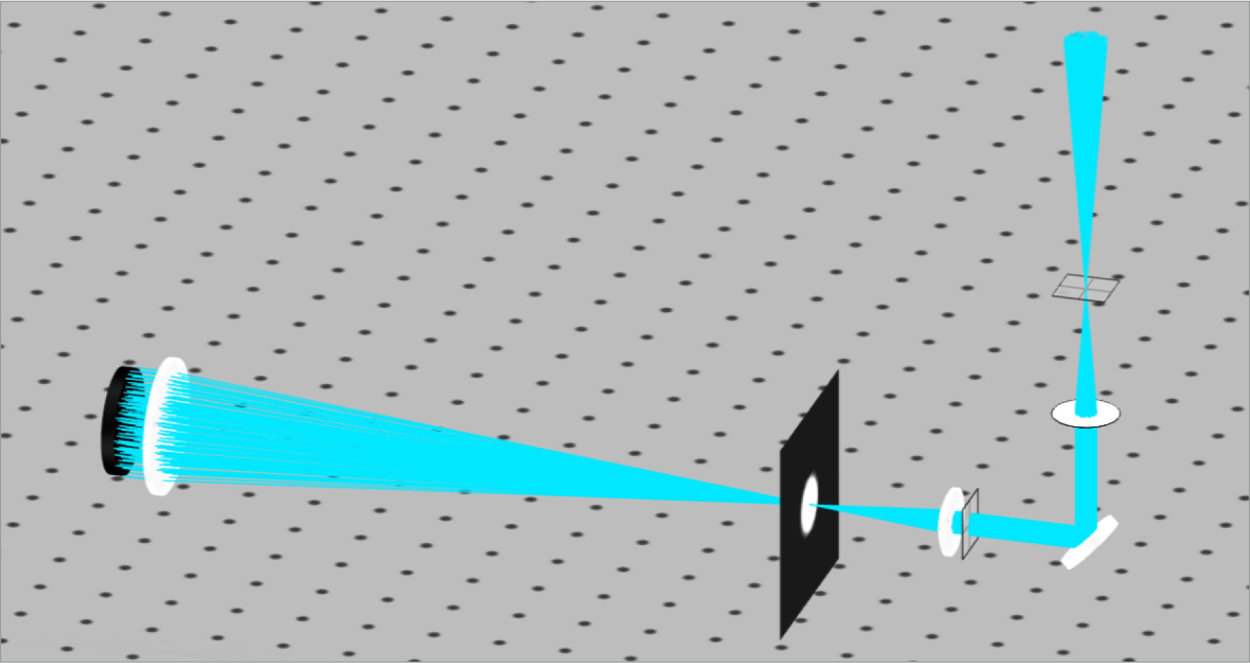
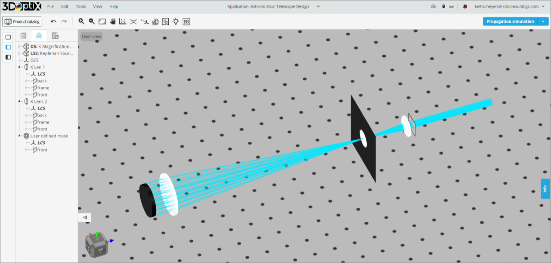
Looking at the image of our optical system, we can see that we have parallel rays entering and exiting the system. Since astronomical viewing occurs over incredible distances, the rays of light at each angle will be collimated. Therefore, we desire a collimated output so that our eye or a camera can image the scene.

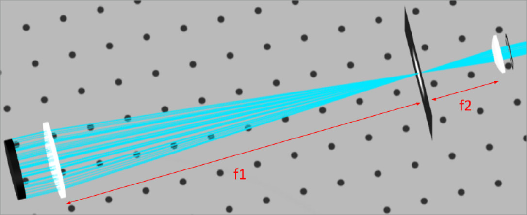
For positioning the lenses and determine system performance we can use the simple equations below:

  • Lens Separation:D = f_{Objective} + f_{eyepiece}
  • System Magnification: M = \frac{f_{System}}{f_{eyepiece}}

We can see immediately from the image above and the lens separation equation that the positive lenses make the length of the telescope longer than using a negative lens. Negative lenses are used in Galilean telescopes, but they are typically for terrestrial viewing.

Notice that the Kepler telescope is actually benefited from the longer system focal length with increased magnification.

Below are the calculated parameters of the systems. We will later add in more components to complete the design, but for now we will take as fact that the additional components will add 150 mm to the system focal length. The system focal length is the path length from the objective lens to the eye/camera.
This will be shown further down in the analysis.

  • Lens Separation:D = 250mm + 50mm = 300mm
  • System Magnification: M = \frac{(300mm + 150mm)}{50} = 9.0x

Now that we have our starting parameters calculated we shall analyze the collimation from the on axis collimated light. 

We will add an extra detector 100 mm behind the first detector. This will allow us to determine if the lenses are positioned so that collimation is achieved at the output of the eyepiece lens.

The lenses will then be positioned at the nominal placement and the spot size at each detector measured. 3DOptix analysis windows have a useful tool to measure spatial intensity patterns that is quick and easy to use. We also have the ability to download the detector pixel data for external analysis in a software of our choice, but the measurement tool is a quick and easy option.
Depending on the geometry of your source either circle or square can be selected to get a true estimate of the dimensions for the beam. The fit to circle option will be selected and three points along the edge of the beam must be chosen. The tool will automatically create a circle and generate statistics.
As can be seen by the statistics generated, the two detectors are measuring the beam radius to be very close in size at the two locations; 3.95 mm and 4.02 mm. This means we are very close to collimation and at a good starting point for our telescope. The lens separation was changed to 299 mm as this gave a better result than 300 mm.
Up to this point we have not included all the components necessary for the Kepler telescope. We still need to include the image correcting mirror to flip the image, focusing lens, and a detector to analyze the system as a whole. We will simulate a camera with a 25 mm focal length lens and a 10 mm rectangular focal plane array to form the image.
An ideal reflective mirror and paraxial lens have now been added and we have the full system built. The next task will be to verify the image is upright using the mirror and detector position.
To determine that the image is not flipped we will use an aperture mask right after the light source. The paraxial lens will be removed since we want to see the afocal output of the image. We can now observe the image at two points; behind the eyepiece and at the image plane.
Observing the image at the two points in the system, we can see that behind the eyepiece the image is flipped, while at the image plane, it is restored to its original orientation. The image below on the left shows the flipped image after the eyepiece lens, and the one on the right the corrected image after the mirror and paraxial lens.
Flipping the image can be accomplished with a more complex system to output the correct orientation to the user at different viewing positions. We can reinsert the paraxial lens back into the optical path and remove the mask.
Finally, we are going to change the light source to output an “RGB” spectrum to observe the chromatic aberration present in this simple telescope design.
As can be seen from the images of the individual wavelengths, the spot sizes at the image plane are different diameters which will create a halo effect. This is due to the different refractive indices for the three wavelengths. This is a downside to a fully refractive system that doesn’t use color correcting optics such as achromats.
We have completed the initial analysis of our Kepler telescope and are ready for further analysis and optimization. From what has been accomplished so far, there are a few parameters we know we need to correct to create a better image. The many features and analysis methods available are extremely useful to developing these types of systems even further.
mascot-1-1

3DOptix works
only on desktop!

Please go to 3doptix.com on a
desktop device, using the
Chrome or Edge browser

Available on January 30th, 2023